This week, one of the most important ythings we talked about is "Throughput versus Latency". We gave the post office versus DSL example. (See the reading material at the bottom.) We talked about the number of cycles required to do a block write to DRAM, block read, and block increment.
We went over FSM design. This is something you must have covered in your Digital Design course. This course assumes you remember what you learned in that course and does a quick review. In the later part of the week, we covered a very basic interface protocol called "valid/ready" handshake. This protocol is commonly used in synchronous digital chips.
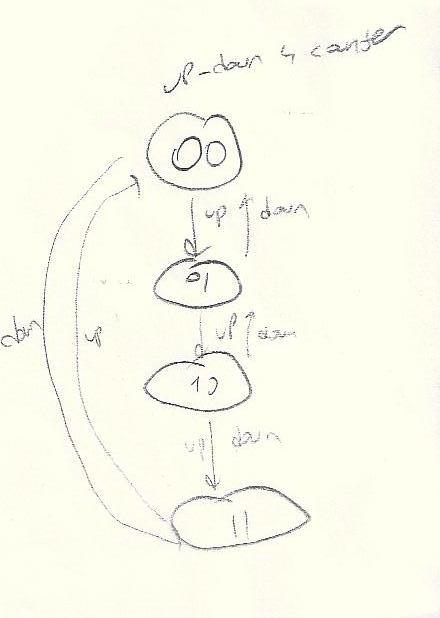
FSM stands for Finite State Machine. In short we call them "state machine". The simplest state machine one can imagine is a 0/1 counter. (See Fig 3.1.1 of wk3_handout1.) A 0/1 counter (also called 2-counter because of the two distinct states) produces a signal which is half the frequency of the clock. A 3-counter, on the other hand, can be used to divide the frequency of a clock by 3. (See here an up-down counter that counts between 0 and 3.)
A state machine has bunch of flops and gates {ie. combinational
logic). (See Fig 3.1.2 of wk3_handout1.) A
circuit which has memory can also be thought of as a state
machine. However, since a memory an represent many many states, the
number of states becomes infinite for pratical purposes.
Exercise: Imagine a memory that has 4 locations. Each
location has 8 bits. How many states (ie. different values) can this
memory hold?
Answer: This memory has 4x8=32 bits. It can hold
232 (roughly 1 billion) states.
State machines are also used in SW. They are especially important if you are writing a parser for a computer language such as C. A compiler has various parts. A parser is the first part. It takes the text language input and places it into data structures after a recognition process. Then, the actual compile stage creates object-code and the linker links object-codes to create an executable file.
Exercise: Design a state machine which recognizes a sequence
of 110. The input to this state machine is 1 bit each clock cycle. The
output is also 1 bit. I want this state machine's output to go high as
soon as it sees the last bit (ie. 0). Once 110 is seen at the input,
the output is supposed to go high and stay there.
Answer: See wk3_handout1.
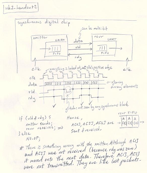
This interface is the simplest interface used by chip designers to send data from one chip block to another in synchronous chips. That is to say that the two blocks are assumed to run on the same clock. This interface is not an official standard. As a result, it does not even have a standard name. It is often called a request/acknowledge interface. However, that name is misleading, because the interface is rather a valid/ready interface (Vld/Rdy i/f). The reason we will talk about this interface is that it illustrates some basic concepts we will need when we study standard interface protocols. Every experienced chip designer in Silicon Valley and the rest of chip industry knows and uses this interface. In Vld/Rdy i/f, data is exchanged when both vld and rdy are active. (See wk3_handout2 for details.)
Valid/ready interface is commonly used in chips. It is a "point to point" interface: one sender and one receiver. One draw-back of this interface is, it may not run at high frequencies because of the combinational path between the two blocks. One alternative is a "credit-based interface".
In this type of interface, we still have a vld signal. However, rdy is replaced by a "credit" signal. For every clock cycle in which credit is high, we understand that the receiving block can accept one data from the sender. Every time the receiver drains a data, it raises credit signal for one cycle. The sender counts the number of cycles credit is high. Every time credit is high, it is like the receiver sends a gambling chip (ie. kumar fishi in Turkish) to the sender. And every time the sender sends a data to the receiver, it is as if it spends one gambling chip. In this interface, data is sent when vld is high. The sender will not assert vld unless it knows the receiver can accept data.
Reading material summary:
wk3_handout1: FSM that recognizes
110.
wk3_handout2:
Valid/ready interface.
wk2_handout3: Pages 24-end.