EENG3010 (week of Mar 27-31)
UARTs have FIFOs in them. So do many chips and hardware
blocks. However, a FIFO is not a purely hardware concept/entity. FIFOs
are used in SW as well. In SW world, they are simply called
"buffer". A buffer does not strictly mean FIFO but many times when
people use the term buffer, they mean a FIFO. FIFO means "First In
First Out". Some of you confuse it with LIFO -- which means "Last In
First Out". LIFO means we read (hence output) the last one we put in
(ie. wrote). Hence a LIFO is the same as a "stack". A FIFO is instead
q "queue". Or you may call it a pipe. FIFOs tie loosely coupled
blocks/processes to each other. Such as the two sides of a UART -- the
external world and the inside of the PC. Such as the USB host
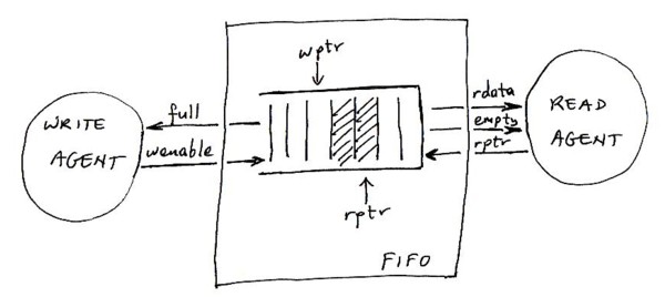
controller on a PC (with DMA) and the CPU. For ex. when the USB chip
on your PC (the host controller which comes as part of the USB root
hub) detects that the USB devices are in need to send data to the PC,
it sends an interrupt to the CPU. Then the CPU instructs the USB chip
to DMA (Direct Memory Access) to the system RAM. The USB chip writes
the data it receives at the write pointer's location in a device
buffer. Whenever the CPU is available, it reads the first data on top
of the bufer (ie. at the read pointer).
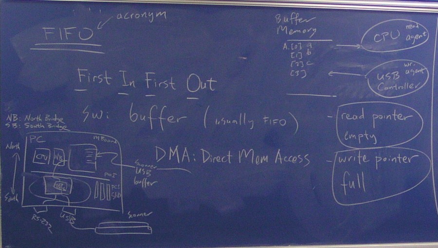
You may also see what we drew on the board
in the class. If you are having difficulty reading it, the circled bus
south of the PCI bus is the USB controller chip and is connected to a
scanner outside the PC thru the USB port. Here is
a piece of code which shows the behavior of a FIFO.
PS/2 port
PS/2 stands for IBM Personal System 2. IBM first had the IBM
PC. Then released IBM PC XT followed by AT. Later, they released
PS/2. PS/2 was not an open architecture unlike XT and AT. Today's PCs
are based on the AT architecture. However, they took the mouse and
keyboard port of PS/2 and called it PS/2 port. Earlier mice and
keyboard were hooked up through serial ports (ie. RS-232).
PS/2 port is some sort of a synchronous port. It has a small
form-factor and fewer pins compared to serial port. Make sure you read
this page
and find out how PS/2 port works. With the clock in PS/2 port, we do
not have to worry about synchronization. The PS/2 port is half-duplex
whereas RS-232 is full-duplex. That is to say that with PS/2 port PC
and device cannot talk at the same time. Note that, if no data is
exchanged, the clock does not pulse.
In reality, mouse was invented at Xerox Palo Alto (California)
Research Center. (Xerox was the world's biggest maker of
photocopiers.) Xerox is the place where Windows OS, Ethernet, and the
first personal computer (ie. PDP-11) were invented. Apple Computer
stole a windows-based OS concept and mouse from Xerox and created the
world's first true PC "Macintosh" in early 80's. Later on, Microsoft
stole the windows concept from Apple and introduced Windows to the
world's IBM PC compatible users in late 80's.
The iron ball in a traditional mouse can move in any direction. The
x and y components of the movement vector are extracted by two
cylindrical rollers. (See the picture in the above Wikipedia link.)
One roller only moves in the x direction and the other in y
direction. The distance they move are the components of the iron
ball's movement. As a roller moves, the holes on the roller moves
acros an LED (ie. Light Emitting Diode). The LED's light pulses as a
result when viewed by photodetector. The output of the photodetector
hence contains pulses. The number of pulses in that signal times a
distance unit gives us the length of x or y component.
The keyboard is also connected to a PS/2 port on the PC. Hence,
same pinout as the mouse port. However, the data transferred is
different. If we switch the ports of the keyboard and mouse, they
won't work. This is a slight oversight on IBM's side. To prevent
mistakes, they color-code the two ports. Mouse port is green and the
keyboard port is purple. Here is how a keyboard works.
The basic idea is that when we push a key, we short-circuit a wire
and hence the microcontroller in the keyboard senses a different logic
level. However, with approxiamtely 100 keys, we would need 100 wires
with this scheme. 100 wires would be hard to route. Much more
importantly, we would need a microcontroller with more than 100 pins
and the cost of a keyboard would be high.
Engineers found a very smart solution for this. Keys are above a
matrix of wires. There are X wires and Y wires. A key, when pressed,
short-circuits an X wire and a Y wire. This way 100 keys require a
matrix of 10 by 10 and hence 20 wires. Let's say when we push A, we
short-circuit X1 and Y2 wires. That does not mean we short-circuit X1
to Y2. Instead, we close the switch on X1 and separately we close the
switch on Y2 as well. So the microcontroller sees a 1 on X1 and
Y2. This way, the microcontroller can tell the coordinate of each
key. There is a slight problem with this technique. If we push two
keys simultaneously, we cannot tell exactly which keys are
pushed. Let's say we have X1, X2, Y1, and Y2 wires. A, B, C, D keys
are at respectively (1,1), (1,2), (2,1), and (2,2) coordinates. If all
the 4 wires are pushed, we cannot tell if the user is pushing A-D or
B-C. In addition we cannot tell if only two keys are pushed or even
three keys are pushed at the same time. This is not much of a
problem. First of all only certain 2-key and 3-key combinations are
valid.. Secondly, in a keyboard there are multiple matrices. If the
multiple keys that are pushed are in different matrices, there is no
problem anyway. Also, it is very unlikely that keys are pushed exactly
at the same time. In that case, we can tell which keys are pushed. For
ex. A is pushed first and kept pushed, and then D is pushed. Then,
they are released one by one. From this sequence, the keyboard driver
can tell which keys are pushed.
Speaking of pushing and releasing keys, the keyboard sends a unique
"scan code" to the PC each time a key is pushed or released. When a
key is released, the key's scan code is sent again but is preceded by
a fixed release code.
We started this part of the lectures by mentioning the PC monitor
uses a DE-15 connector. The DE-15 connector is the high-density
version of the DE-9 connector used on the PC serial port. That is to
say that it is the same size but has more pins. We defined the signals
on the 15 pins. Actually one pin is always missing on the monitor
connector. We then said the PC monitor is a CRT
(ie. Cathode Ray Tube) just like a TV set. We explained how a CRT
works. Horizontal sync and vertical sync. Later on we explained what
interlaced and non-interlaced means. Then, we moved into a discussion
of RGB. Then, we said if
you look at Display in Control Panel on your PC, you will see 16 and
32 bit modes. These are, in fact, 15 and 24 bit modes. The rest of the
bits are unused. 15=3x5 and 24=3x8 bits. This is to say that in 16 bit
mode RGB are each 5 bits. And in 32 bit mode, each color component is
8 bits. The reason we are wasting bits and hence we have 16 and 32 bit
modes is computer RAM has 32 bits in each word. This way, pixels are
aligned to RAM addresses. Then, we said if we compare RGB=(1,1,1)
versus RGB=(2,2,2), both are the same color and the latter has more
brightness. Hence, 24 bits does not necessarily mean 2^24 distinct
colors. However, it at least means we theoretially have 2^16 disctinct
colors. (We are fixing the value of R for ex. and modifying G amd B
components, and hence get different ratios.)
Last but not least, we mentioned the PC monitor interface is an
analog interface. We said this is a little awkward because everything
in the PC up to the interface is digital. We explained why this is so
by calculating the required bit rate. Let's say we have a screen
resolution of 1152x864. A refresh rate of 70Hz at 24 bits (32 bits)
per pixel. That is approx. 1M pix/frame * 70 frames/sec * 24 bits/pix
= 1.7 Gbps. With tramsmission overhead (packet headers and so on) we
are talking about 2Gbps. Until Gigabit Ethernet became popular, we did
not have any cheap digital interface at Gbps rates. However, even now
we do not have any cheap digital interface at 2Gbps rate. Even if the
required rate was 1Gbps, the extra cost of using a Gigabit Ethernet at
the monitor interface is prohibitive. We also looked at why we have
separate ground pins for RGB. We said since these are high-rate analog
signals we do not want to couple them. It is OK if RGB is transferred
in analog becuase it is OK if the monitor displays a slightly
different color. We are not transferring a file across the monitor
interface. Like audio, video can shift a little bit in color and
location. However, it should not shift across lines and frames. This
is achieved by horizontal and vertical sync signals.
Misc. PS/2 Port Discussion
I want to say a few things about the questions I received during
the lectures this week.
When I mentioned, you cannot connect the keyboard to the mouse port
on the PC and vice versa, someone said how come laptops have a single
PS/2 port for external mouse and keyboard. I guess the chip in a
laptop that controls the PS/2 port is more intelligent and more
expensive. I believe this chip reads the deviceId register off of the
PS/2 device and that is how it can tell if it is a keyboard or mouse.
Then someone asked how a touchpad works. I was asked if it also has
a matrix of wires underneath. I don't know about wires but most
touchpads, it turns out, have a matrix very small capacitors under
them. At a given point we are not pressing on two capacitors, we are
pressing on a single capacitor at that point and changing its
capacitance and hence the current. That is how the touchpad can tell
where we are pointing. I have also researched touch screens. It turns
out there are mainly 3 types: resistive, capacitive, and
SAW-based. Resistive is like a matrix of wires and hence like the
keyboard. Resistive is the cheapest and has the worst picture
quality. Capacitive is like a touchpad. Capacitive is a little more
expensive and slightly better picture quality. SAW-based means surface
acoustic waves. This type is the most expensive and the one with the
best picture quality.
Required reading material:
See notes on the board for PS/2, mouse, keyboard, video.
Mouse.
Keyboard basics: A must-read.
PC Video: reading1, reading2, reading3.